

Top 10 Split-Core Residual Current Transformers for Precise Leakage Current Monitoring
2026-10-30
How precise is your leakage current monitoring, really? If you’ve ever chased nuisance trips or struggled with inconsistent readings, the split-core residual current transformer you choose is probably the culprit. This roundup covers ten models that deliver the accuracy and stability needed for reliable protection—including a closer look at Xiasen, a brand that consistently surprises engineers with its build quality and performance. By the end, you’ll have a clear sense of which units are worth your time and which are just marketing noise.
What Separates a Reliable Split-Core Residual Current Transformer from the Rest
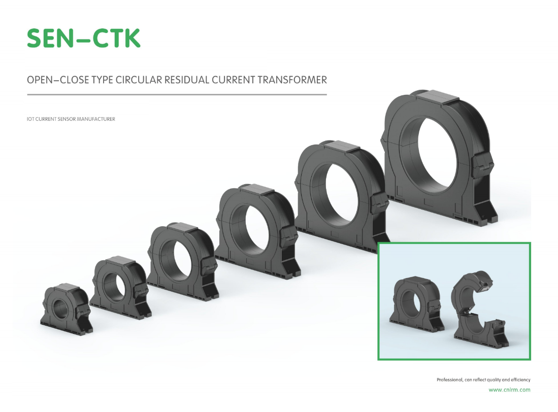
A split-core residual current transformer might look identical to its competitors on a spec sheet, but field performance tells a different story. The first thing that separates a dependable unit is how the two core halves mate. Cheap designs rely on a simple hinge and hope the air gap stays constant; better units use precision-ground mating surfaces and a clamping mechanism that maintains even pressure every time the CT is closed. If that gap shifts by a few microns, the magnetic path changes and the residual current reading drifts.
Beyond the mechanical fit, the core material and shielding make a practical difference. High-permeability nanocrystalline or permalloy cores hold their accuracy over a wider temperature range, which matters when the CT sits inside a distribution panel that heats up under load. A reliable transformer also includes internal magnetic shielding so that current flowing in adjacent phases doesn't couple into the residual measurement. Without it, nuisance trips become common and technicians start distrusting the protection system.
Long-term reliability comes down to how the unit handles moisture, vibration, and repeated opening and closing. Conformal coating on the windings, sealed output leads, and a corrosion-resistant clasp are not luxury features; they are what keep the residual current signal accurate after five or ten years of service. Manufacturers that only verify performance on a bench at room temperature often miss these failure modes. The transformers that hold up in real installations are the ones engineered for the worst conditions, not just the nominal case.
The Role of Core Material and Winding Consistency in Leakage Accuracy
Magnetic cores are rarely identical from batch to batch. Small shifts in permeability, saturation flux density, or even thermal aging behavior can nudge the leakage field in unexpected directions. Ferrite cores, for instance, tend to have tighter initial permeability tolerances than powdered iron, but their temperature coefficient can still introduce measurable drift in leakage-dominated designs. When the goal is a repeatable leakage value, selecting a core material with low sensitivity to operating temperature and a narrow tolerance window matters more than chasing the highest possible permeability.
Winding consistency is equally decisive. The way turns are laid down—layer progression, tension, insulation thickness, and the physical gap between primary and secondary—directly shapes the coupling coefficient. Two transformers built on the same core geometry can show noticeably different leakage if one has slightly looser windings or an uneven traverse. Automated winding with controlled tension and fixed interlayer margins helps, but even small variations in wire diameter or bobbin deformation can shift the leakage percentage by a fraction that matters in resonant converters or current-sensing circuits.
What often separates a stable design from a marginal one is how well these two factors are matched. A high-permeability core cannot compensate for sloppy winding, and perfectly layered windings will not rescue a core that drifts with temperature. In practice, this means sorting cores by measured A_L value and pairing them with windings made on the same machine setup, with periodic checks of the actual leakage rather than relying on calculated estimates alone. That combination keeps leakage accuracy within the narrow band that high-frequency power stages and precise current transformers expect.
How to Judge a Split-Core CT Before It Reaches Your Panel
Before a split-core CT gets wired into a panel, start with a close visual and mechanical check. Look for any hairline cracks or warping on the housing that could let moisture in. Open the core a few times and feel how the mating surfaces line up—any grit, rust, or uneven gap will throw off the magnetic path. Make sure the hinge and latch don't wobble, and verify the core closes with a solid, even contact. If the jaws don't meet cleanly, accuracy is already compromised before you ever bolt it in place.
Electrical verification is where many installers skip steps. Use a low-voltage excitation test or a handheld CT analyzer to check ratio, polarity, and saturation behavior. Don’t rely only on the nameplate—many split-core units arrive mislabeled or with secondary leads swapped. Short the secondary terminals and run a quick insulation resistance check between the core and secondary winding to catch any internal shorts. If the secondary labels are faded or the polarity marks don’t match your tester, mark them clearly before installation.
If a bench setup is available, run a loop test before the CT ever reaches the panel. Pass a known current through the primary window and compare the measured secondary output against the expected ratio. Watch for non-linearity or phase shift at low currents—split-core units often struggle there. Thirty seconds on a bench can reveal a bad unit that would otherwise cause nuisance trips or skewed metering once the panel is energized.
Why Installation Angle and Gap Alignment Change Everything
Most people assume that as long as a component is screwed down tight, the job is done. That assumption quietly falls apart the moment you look at how the angle and the gap work together. A slight tilt in the wrong direction can trap moisture instead of letting it run off, while a gap that is even a few millimeters off invites debris to collect or causes uneven load distribution. These two factors don't act separately—they compound each other until small errors become visible, expensive problems.
Think about what happens when the installation angle forces water to pool near a seam. No sealant on earth will save you if the gap alignment keeps pulling the seam apart every time the material expands and contracts. Conversely, setting the angle correctly but ignoring the gap can leave edges proud or recessed, which creates a catch point for wear and tear. The difference between a setup that lasts ten years and one that fails in two often comes down to how carefully these two variables were dialed in during the first hour of work.
Once you start treating angle and gap as the primary controls rather than afterthoughts, the whole installation begins to make sense. You stop shimming, forcing, and hoping. You start measuring from the same reference point, checking the gap at both ends, and adjusting the angle before locking anything in place. That shift in approach changes not only the finished result but also the time wasted on callbacks and repairs.
Real-World Leakage Currents That Most Transformers Miss
Engineers often rely on datasheet leakage current specs measured at 60 Hz with a clean sinusoidal input, but real installations rarely look like that. When a transformer is driven by a variable frequency drive or inverter, steep voltage edges (dv/dt) couple through inter-winding capacitance and produce spike-like leakage currents far beyond the steady-state value. Those spikes can trip ground-fault protection, corrupt sensitive analog signals, or slowly degrade insulation through partial discharge even though the 'spec' says leakage is a few milliamps.
Another overlooked source is common-mode leakage returning through the chassis or protective earth. In medical equipment or laboratory setups, multiple transformers share a ground reference; tiny differences in winding geometry and parasitic capacitance create circulating currents that don't show up in a single-unit bench test. Humidity, dust, and temperature cycling further change surface leakage on terminal blocks and varnished windings, so a transformer that passes a factory hipot test may leak significantly more after six months in a coastal or high-vibration environment.
The most dangerous cases combine low-frequency leakage with high-frequency noise. For instance, a transformer feeding a switched-mode supply can develop resonance between its leakage inductance and the input capacitance of the rectifier, amplifying current at a few tens of kilohertz. Current clamps and true-RMS meters often miss these narrow pulses, giving a false sense of safety. Checking leakage with an oscilloscope and a high-bandwidth current probe—under actual load and temperature—reveals what most transformer datasheets don't.
Matching the Transformer to Your System Without Overpaying for Specs
Choosing the right transformer often comes down to a simple question: what does your equipment actually pull, and what will it realistically pull in the future? A lot of buyers end up with oversized units because they confuse peak surge capacity with continuous load. That mistake can cost you hundreds of dollars upfront and more over time in wasted no-load losses.
Start by listing every device the transformer will feed, then check the nameplate ratings. Add up the continuous watts or volt-amps, not the startup spikes. Most modern electronics and motors list both, but the running current is what matters for sizing. If you have a motor that draws 12 amps on startup but only 4 amps while running, a transformer rated for 12 amps is overkill unless that startup surge happens constantly.
Also look at your incoming line voltage and the required output. A transformer with a wide input range might seem like a bargain, but if your supply is stable at 120V, paying extra for a unit that handles 90–264V is wasted money. Stick to the voltage you actually have, with a small safety margin for brownouts or fluctuations. Match the kVA rating to your total continuous load plus about 20% headroom, and you'll avoid both under-sizing failures and over-priced "future-proofing."
FAQ
Split-core units can be installed without disconnecting the main conductor, which is a practical advantage in live panels or crowded wiring. They also allow retrofitting in existing installations where interrupting power is costly or unsafe.
Most quality split-core residual current transformers offer accuracy between 0.5% and 1% at rated current. For very low leakage levels, look for units with high permeability cores and low phase shift, as these maintain precision near the lower end of the range.
It surrounds all phase and neutral conductors and sums their magnetic fields. Under normal conditions, the net current is zero, so no output is produced. When leakage occurs, the imbalance creates a small secondary current proportional to the fault.
One frequent error is leaving a gap between the core halves or allowing dirt to accumulate on the mating surfaces. Another is routing only some conductors through the aperture, which causes false readings. Always confirm the core closes tightly and all live conductors including neutral pass through.
Standard split-core residual current transformers are designed for AC leakage at 50/60 Hz. For DC or mixed AC/DC systems, you need a different technology such as fluxgate or Hall-effect based sensors.
They need very little ongoing care. Periodic visual checks for debris, corrosion, or loose mounting hardware are usually enough. In dusty or humid environments, cleaning the core faces once a year helps maintain accuracy.
The aperture must accommodate all current-carrying conductors without crowding. Also match the rated residual current range to your expected leakage levels, as oversizing can reduce sensitivity at low faults while undersizing may saturate the core.
Conclusion
Most split-core residual current transformers look similar on a spec sheet, but the ones that perform well in the field share a few quiet traits. The core material and winding consistency determine whether a 5 mA leakage signal gets captured cleanly or disappears into noise. High-permeability cores with uniform winding tension keep the ratio stable across temperature and vibration, while sloppy layering creates hotspots where accuracy drifts. Before a unit reaches the panel, you can spot trouble by checking the mating surfaces for flatness and looking for any sign of gap variation—the smallest air gap changes the magnetic path and shifts the trip threshold. Installation angle matters just as much; if the core halves aren't parallel or the locking mechanism lets the gap open slightly, a transformer rated for 30 mA can easily miss a 20 mA fault. Real-world leakage often includes harmonics, DC offsets, and short bursts that cheap CTs filter out or saturate on, leaving protection blind.
The best picks in this category aren't the ones with the longest datasheet; they're the ones that match your system's actual leakage profile without forcing you to pay for bandwidth you'll never use. For a 50 Hz industrial panel, a transformer with a 0–2 kHz response is plenty, while a VFD-driven load may need a wider window to catch high-frequency leakage before it becomes a shock hazard. Look for units that specify accuracy from 10% to 100% of rated residual current, not just at full scale. Also check whether the split-core design holds its gap alignment after repeated opening and closing—some hinges wear quickly and introduce an offset that drifts over months. A worthwhile transformer will give you a stable output with no need for frequent recalibration, and it will handle moderate temperature swings without derating. Ultimately, the top performers are those that stay boringly consistent in the real world, not just on the test bench.
Contact Us
Contact Person: Liu Mengyang
Email: [email protected]
Tel/WhatsApp: 8618727589233
Website: https://www.cnlrm.com/en/