

Fiber Optic HDMI Cable ODM: How Custom Manufacturing Shapes High-Performance AV Connectivity
2026-11-16
Most HDMI cables barely survive a year of daily use. Yet the demand for 4K and 8K video keeps pushing copper to its limits. That is where fiber optic HDMI cable ODM steps in, turning a simple accessory into a precision-engineered link. For brands that need reliable, long-distance AV transmission without bulky repeaters, custom manufacturing is no longer a luxury. EBCYX has spent years refining this process, helping partners ship cables that actually hold up in real installations. In this post, we look at how ODM decisions shape signal quality, durability, and your product's reputation.
Choosing Glass That Can Carry 8K Over the Longest Pulls
Most 8K failures at long range don’t come from the display or the source; they come from glass that was fine on paper but wrong for the route. A 48 Gbps FRL signal leaves almost no room for attenuation, so core size, modal dispersion, and connector loss stop being specifications and start being the whole job. Copper gives up early, multimode works for shorter runs, and single-mode starts making sense once the pull passes the kind of distance where a ladder is already out.
What separates a reliable long pull from a gamble is rarely the fiber alone. It is how the cable handles tension at the head, how sharply it can turn inside a conduit without leaking light, and whether the termination stays put after someone has tugged it through a ceiling. A cable that uses good glass but a stiff, kink-prone breakout will still bring an 8K link down in the field.
For 8K over the longest stretches, look for a low-loss path with serious strain relief and test it under real bending conditions before the walls close up. Single-mode glass inside a well-built hybrid cable tends to outlast the install, while generic multimode claims often fall apart once the signal has to travel past a few corners and a hundred feet of conduit.
Machining Connector Shells for Tight Rack Spaces
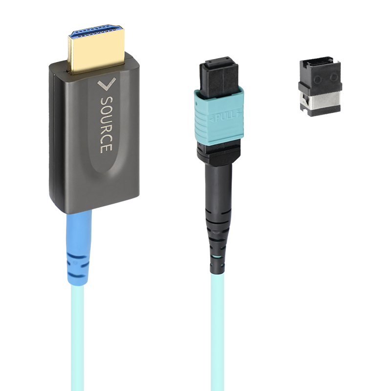
Working with connector shells bound for high-density rack setups usually means throwing out assumptions about generous clearances. A shell drawn at 0.75 inches across can still carry a flange, a keyway, and two O-ring grooves that leave only 0.020 inches of wall in places. On the mill, the first job is often not cutting metal but sorting out how to hold the part without crushing that thin section. Soft jaws bored to the unfinished OD have worked better than standard V-blocks, especially when paired with light axial clamping. Turning and milling get blended deliberately here; skipping the second setup avoids the tiny misalignment that turns a precision shell into a scrap piece once it hits the rack rail.
Burr control gets overlooked until a connector refuses to seat. For these tight spaces, a small chamfer on the leading edge of the shell does more than ease insertion. It also prevents rolled-over material from binding against the panel cutout. We have had good results cutting the internal thread and external bayonet features in the same operation, then using a fine-grit nylon brush pass to break edges without opening up tolerances. Keeping the surface finish around 32 Ra on mating diameters is usually enough, but the real test comes when the shell is fitted to a rack with adjacent ports already populated—there is no tolerance for the housing to grow even a few tenths.
Keeping Signal Skew Out of Multi-Channel AV Installations
In multi-channel AV work, signal skew rarely announces itself until a source looks soft or a presenter's voice seems to wander off-mic. The problem starts when two or more signals that left a source together arrive at the display or processor at different times. With video, that often shows up as color fringing on fine text or edges; with audio, it can thin out the stereo image or make a phase relationship feel unstable. None of this is obvious during a quick bench test, which is why installers often only discover it after the room is finished and the furniture is in place.
The usual suspects are easy to overlook. A long run of coax next to a short Cat6 path, an HDMI extender that buffers one channel differently, or a matrix switcher that re-clocks only part of the signal can all introduce just enough delay to matter. Even cable batches that look identical on the reel can behave slightly differently once they are pulled through conduit and terminated under less-than-ideal conditions. The key is to treat skew as a measurable timing error, not as a vague sync issue that gets blamed on a source device.
A practical fix starts before the rack is built. Keep cable lengths matched for each channel in a distribution run, and if a product offers skew compensation, use it while viewing a proper test pattern rather than after the fact. For analog video, a small adjustable delay box or a processor with per-channel timing controls can nudge things back into place. For digital AV, re-clocking distribution, active extenders with equalization, and verifying firmware across all endpoints can prevent the partial delays that cause the problem. The goal is not perfection down to the nanosecond; it is to keep the arrival times close enough that the display and the listener never need to work around the installation.
Stress Testing the Jacket Before the Cable Reaches a Wall
Most jacket failures near a wall start before the cable ever touches the penetration. The last few feet often carry the sharpest bend, the hardest pull, and the most concentrated clamp pressure, so a jacket that looks fine on the reel can split as soon as it meets the transition. A quick stress check in that exact zone makes sense: flex the cable to the tightest radius it will see at the wall, hold it for a few seconds, then look closely at the surface for whitening, cracking, or any separation from the inner layers.
Cold weather changes the result. A jacket that stretches cleanly at room temperature can turn brittle near freezing and snap under the same load. If the install is happening early in the morning or in an unheated chase, let a sample sit at that temperature before testing. Pay attention to the inside of the bend, not just the outer face; compression wrinkles there can be the first sign that the jacket is trying to buckle before the cable even reaches the connector.
When the test does show damage, the fix is usually not a thicker tape wrap. Shorten the unsupported length, open the bend radius, or add a flared bushing where the cable enters the wall. Then repeat the same bend-and-pull sequence. The cable should survive the harshest angle it will experience before it disappears into the wall, not after.
Balancing Speed and Scrap Rates on the Assembly Line
Rushing a line to hit hourly targets often looks good on the morning report until the rework bins start filling up. A ten percent gain in cycle time means nothing if five percent of the units come back with bad welds or misaligned brackets. The real skill is knowing which stations actually benefit from extra seconds. A torque sequence that gets skipped under pressure may not fail immediately, but it becomes a warranty claim three months later.
Plant engineers tend to talk about scrap as a cost of doing business, but the best line supervisors see it as a signal. When scrap rates climb at one station while output stays flat, that station is telling you its operators are compensating. They are not lazy; they are buying speed with judgment calls. Giving them a visual gauge or a simple go/no-go fixture often removes the guesswork faster than another training session.
There is no universal number that balances both sides, but a useful rule is to watch the ratio of first-pass yield to takt time over a full shift, not just a thirty-minute sprint. Lines that hold steady scrap rates during the last two hours before break usually have the balance right. The ones that spike at 10 a.m. and again at 2 p.m. are running on adrenaline, and that never lasts.
How Custom Packaging Prevents Microbends in Transit
Microbends don’t announce themselves with cracks or snapped jackets. They form when a fiber cable flexes against a hard edge, gets pressed under stack weight, or vibrates inside a loose carton, creating tiny axial distortions that scatter light and quietly eat into signal integrity. Custom packaging attacks that problem by shaping the interior around the actual cable dimensions, so the product sits in a controlled position instead of drifting into corners or resting on rigid contact points that encourage localized stress.
Foam density, cavity depth, and wall thickness are tuned to the cable’s bend radius and weight. The packaging absorbs shock through progressive compression rather than letting the fiber feel the full force of a drop or pallet impact. In many designs, separated compartments keep multiple reels from knocking against one another, while soft yet resilient cradles spread pressure evenly across the outer jacket, cutting the sharp point loads that lead to microbending over long hauls.
Temperature swings during transit also play a role, since jacket materials contract and expand at different rates than glass. Custom inserts made from closed-cell foams create a thermal buffer, reducing direct contact with cold container floors or sun-heated panels. By keeping each spool suspended, aligned, and cushioned against both mechanical shock and thermal strain, the packaging keeps the fiber’s path as straight at the microscale as it was when it left the production line.
FAQ
The connector housing, cable jacket material, bend relief design, internal fiber type, photoelectric conversion module, and firmware tuning can all be reworked around the brand's installation needs. It is not just a logo printed on a generic cable; the electrical and mechanical details are adjusted before tooling begins.
Copper starts to fight physics beyond roughly 7 to 10 meters for high-bandwidth signals. Attenuation, jitter, and electromagnetic interference rise quickly, forcing thicker conductors or active repeaters. Fiber carries the high-speed lanes optically, so a thin hybrid cable can hold 4K or 8K integrity over 30, 50, or even 100 meters without the same signal collapse.
Firmware controls the DDC channel, EDID exchange, HDCP handling, CEC pass-through, and signal equalization. A tuned build can be matched to a specific switcher, projector, or LED processor, reducing handshake failures and black-screen events that generic cables may trigger in demanding AV racks.
Eye pattern tests, bit error rate checks, insertion loss, and return loss are the starting point. A serious ODM will also run thermal cycling, repeated flexing, connector mating cycles, a broad compatibility matrix with source and display devices, and long-duration stress tests with real content.
Yes. Glass multimode fiber, variations like OM3 or OM4, and plastic optical fiber each change bandwidth, minimum bend radius, cost, and how the cable handles tight in-wall routing. The ODM should select the fiber based on the target distance and the environment where the cable will actually live.
Usually yes, within verified limits. A softer jacket may reduce pull strength, and a very slim connector can restrict heat dissipation around the optical engine. A good ODM will offer proven base platforms and then tune the mechanical details without pretending every request is a brand-new development.
The HDMI interface has low-speed control paths and needs power for EDID, HDCP, and hot-plug detection. Optical fiber cannot deliver that power, so these hybrid cables keep thin copper conductors for control and power while optical fibers handle the high-speed data lanes.
Conclusion
Fiber optic HDMI ODM work rarely starts with a standard drawing or an off-the-shelf bill of materials. The glass selection alone sets the ceiling for distance and bandwidth, especially when 8K signals have to travel through long conduit runs. Vendors that match fiber geometry to the expected pull length can avoid the signal loss that shows up too late on site. Around that glass, connector shells are machined to fit rack spaces where clearance is measured in millimeters, and termination lengths are controlled to keep skew from degrading multi-channel AV systems in control rooms and event venues. Those three choices are not cosmetic; they determine whether the finished cable behaves the same in a studio rack as it did in the sample room.
The less visible stages matter just as much once the design leaves the lab. Jackets get flexed, pulled, and abraded before approval because a clean bench test means little when cable is dragged through a wall or routed behind equipment. On the assembly line, the practical argument is between faster output and higher scrap rates from rushed polishing or epoxy work, and that tension shapes both cost and long-term reliability. Custom packaging closes the loop by limiting movement in transit, which prevents the microbends that can quietly reduce optical performance before the cable is ever installed. A capable ODM treats these details as part of the product, not afterthoughts.
Contact Us
Contact Person: David Yang
Email: [email protected]
Tel/WhatsApp: 8615814734054
Website: https://www.ebcyx.com/