

Automatic Steel Rule Die Bender Machine for Professional Die Making
2026-08-22
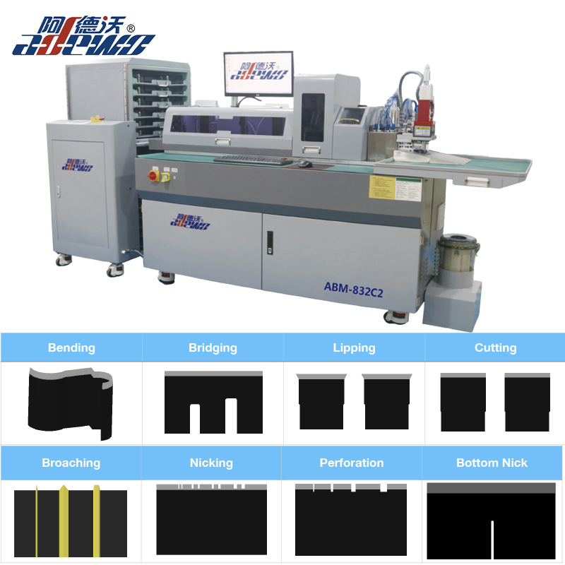
Every professional die maker knows that precision isn’t just a goal—it’s the baseline. The moment you compromise on bending accuracy, you start losing time, material, and trust. That’s where the Automatic Steel Rule Die Bender Machine steps in. Built for shops that refuse to settle, ADEWO delivers a system that turns complex steel rule profiles into repeatable, high-quality results without the usual headaches. In this post, we’ll explore what makes this machine a practical upgrade for modern die making—and why it might be the missing piece on your production floor.
What Changes When You Stop Hand-Bending Steel Rule
One of the first things you notice is the jump in repeatability. Hand-bending a steel rule relies on feel, and even a skilled operator will introduce small inconsistencies from one piece to the next. Once that manual step is gone, every bend follows the same programmed path or fixture stop, so angles and radii no longer drift. For complex shapes with multiple bends, the cumulative error that used to require rework simply disappears.
Production speed also shifts in a way that's easy to underestimate. A tricky three-point bend could eat up ten or fifteen minutes with trial-and-error positioning, checking against a template, then tweaking the curve again. Without that hands-on adjustment loop, the same part is formed in seconds. Operators can run multiple stations or load the next blank while the machine works, which shortens lead times without adding headcount.
There's a quieter change on the shop floor too: fewer strain injuries. Hand-bending steel rule puts constant pressure on wrists, thumbs, and forearms, especially when working with thicker or spring-tempered stock. Removing that repetitive force lowers the risk of long-term musculoskeletal problems and makes the workspace less physically demanding. It also means experienced workers can stay on the job longer instead of being sidelined by hand fatigue.
Why the Clamping System Gets Overlooked (But Shouldn't Be)
In most shops, the clamping system is treated like background noise—present, necessary, but rarely examined. The spindle gets the credit for speed, the tooling gets the blame for wear, and the fixture that actually holds everything in place is ignored until something slips. That's a costly blind spot. A clamp that isn't applying pressure evenly, or has a jaw slightly out of alignment, will quietly steal precision from every cut. You won't hear it fail; you'll just see tolerances drift, surface finishes degrade, and tool life shorten without an obvious cause.
Part of the reason this happens is that clamping looks simple. It's just holding a piece of metal still, right? But the difference between a well-clamped workpiece and one that's merely tight can be several thousandths of an inch—and that's before thermal expansion, vibration, or cutting forces enter the picture. Many machinists learn early on that over-tightening can distort thin-walled parts, but the subtler lesson is that the location, number, and type of contact points matter just as much as the force. A vacuum table, a magnetic chuck, or a set of soft jaws each solves a different problem, yet they're often lumped together as interchangeable accessories.
Ignoring the clamping system also has a safety dimension that doesn't get enough airtime. A workpiece that shifts during a heavy cut isn't just a scrap part; it can become a projectile or snap a tool and send fragments flying. Modern quick-change systems and hydraulic vises have made proper clamping more repeatable, but that doesn't mean it's automatic. You still need to verify contact, check for chips between the jaw and the part, and understand how the cutting forces will try to move the work. When something goes wrong in a setup, the clamping system is often the last thing inspected—and the first thing that should have been.
How the Machine Handles Different Rule Heights Without Adjustments
The machine relies on a floating head design that lets the cutting or pressing element ride along the surface. Instead of locking the working component at a fixed position, a spring-loaded or counterweighted linkage absorbs height differences. As the material passes beneath, the head tilts and shifts in real time, maintaining consistent contact without any manual stops.
Smaller variations are handled by the tool's own inertia and the guide rollers. The rollers sit slightly ahead of the active part and follow the contours first, sending a mechanical signal through a simple lever system. No electronic calibration is needed—the geometry does the work. For taller sections, the head simply lifts; for lower spots, it settles back down, all within a fraction of a second.
This passive adjustment method proves reliable in dusty or wet environments where sensors might fail. It also means operators spend less time dialing in settings between batches. The machine adapts on the fly, so switching from thin to thick stock requires no recalibration or tool changes.
From Flat Rule to Finished Die Form in One Continuous Pass
Traditional die making bends flat steel rule through a series of separate forming stations, each introducing slight deformations that can compound into alignment errors. The continuous pass method eliminates those intermediate steps by running the raw rule through a single, precisely profiled roller set. The metal undergoes simultaneous bending and twisting as it travels, so the final die shape emerges directly from the flat stock without pause.
This approach preserves material integrity because the cross-section is never overstressed at any single point. Instead, the curvature builds gradually along the feed path, controlled by the roll geometry. Operators can switch between die profiles by swapping the roller cassette, which keeps setup time minimal and repeatability high. The finished form retains sharp corner definitions and consistent leg angles, which is critical for clean cutting performance in downstream converting operations.
Adopting a one-pass system also reduces the footprint and energy consumption compared to multi-stage bending machines. There is less handling, fewer transfer mechanisms, and no need for intermediate annealing in most mild steel rules. For short-run or prototype die production, this means a single operator can go from a coil of flat rule to a ready-to-mount die form in minutes rather than hours.
The Angle Correction Trick That Cuts Scrap on First Bends
Most scrap on first bends doesn't come from bad tooling or a worn press brake. It comes from assuming the programmed angle will be right before the material has had a chance to push back. The angle correction trick is to stop treating the first workpiece as a test. Instead, grab a strip of the same sheet—same thickness, same grain direction, same batch if possible—and run it through the die at the planned backgauge position. Measure the actual angle with a protractor or digital angle gauge, then compare that number to the target angle. Write the difference down. That difference is your correction, not a guess.
Once you have the measured error, change the ram depth or angle setting by a small, proportional amount. For air bending, a degree of error often corresponds to only a few thousandths of an inch of punch travel, depending on the V opening. If the first coupon comes out 2 degrees over, pull the punch down a touch and run a second coupon. Keep the first good piece far away from the machine until the second coupon hits tolerance. This two-strip routine catches springback, die wear, and even slight variation in material hardness before a single production blank gets bent wrong. The scrap you save is the expensive, already-cut part that would have been thrown in the bin.
The real trick isn't the math—it's the habit. Store the correction as a setup offset tied to that material lot and thickness, not as a permanent program change. When the next bundle of sheet arrives, clear the offset and test again. Different heats of the same alloy can spring back differently, and a number that worked yesterday can quietly ruin today's first piece. By keeping corrections separate and always verifying on scrap strips, first bends stop being a gamble and start behaving like a known quantity.
Why Die Makers Stop Worrying About Springback After Switching
When die makers transition to servo-driven stamping presses, the long-standing headache of springback quietly fades from daily conversation. Unlike conventional mechanical presses that slam through the stroke at a fixed velocity, servo presses let the ram pause, reverse, or crawl near bottom dead center. That simple control change means the sheet metal can be held under tension just long enough for internal stresses to relax and redistribute. The result is a part that holds its designed geometry without the usual trial-and-error shim work.
Another shift that kills springback anxiety is moving from cold stamping to hot stamping for high-strength steels. Once the blank is heated above its austenitizing temperature and then quenched in the closed die, the material transforms into a martensitic structure that shows almost no elastic recovery after forming. Die makers who spent years compensating with overbend angles and post-form restrikes suddenly find their CAD models match the stamped part within a few hundredths of a millimeter. The dies themselves become simpler because they no longer need complex springback compensation geometry.
The real turning point, however, is feedback from inline measurement systems. When a laser scanner mounted after the press checks every part and feeds correction data back to the die cushion or punch adjustment, springback stops being a mysterious force to fight and becomes a predictable variable to tune out. Die makers stop arguing about whether the simulation was wrong or the steel batch was out of spec. Instead, they read the trend line, make one small change, and watch the next part fall within tolerance. That is when springback stops being a topic of worry and starts being just another number on a screen.
FAQ
It takes steel rule strips and automatically bends, cuts, and notches them into precise shapes needed for die cutting. This removes most of the manual labor involved in making professional cutting dies.
Packaging manufacturers, printing shops, and die-making specialists who need consistent, repeatable bends for cutting dies used on cardboard, corrugated board, leather, or gasket materials.
The machine follows programmed angles and lengths, so you get repeatability within very tight tolerances—often a fraction of a degree. Manual bending can drift with operator fatigue or inconsistent technique.
Most automatic benders accept a range of common rule sizes, typically from 0.71 mm to 1.05 mm in thickness and various heights. The exact capacity depends on the model and tooling you choose.
Basic operation can be picked up in a few days. It usually involves importing a CAD file or entering bend sequences, loading the rule, and monitoring the machine. Some background in die layout helps, but it is not required.
Routine maintenance is fairly straightforward: keeping the bending head clean, lubricating moving parts, and checking the cutting blades now and then. With proper care, these machines run for years without major problems.
It handles the bulk of the work, especially complex or high-volume jobs. Many shops still keep manual tools for quick one-off adjustments or very unusual profiles, but the automatic machine significantly cuts production time.
Standard steel cutting rule works well, including center bevel, side bevel, and serrated rule used for die cutting paper, plastics, foam, and thin metal sheets. The machine is designed for the hardened strip steel found in die boards.
Conclusion
Switching from hand-bending steel rule to an automatic steel rule die bender machine for professional die making changes the entire rhythm of the shop. What used to require repeated manual nudges and constant checking now happens in one continuous pass—flat rule feeds in, and the finished die form comes out without stopping to reposition or re-clamp. A significant part of that consistency comes from the clamping system, which rarely gets attention but directly controls how firmly the rule sits during each bend. Once that grip is dialed in, the machine holds the same pressure every cycle, so you stop chasing small variations between pieces.
Another shift shows up in the angle correction trick. Instead of compensating by feel, the machine applies a preset overbend and pulls it back just enough to land on the intended angle. That removes most of the scrap from first bends and makes springback a background concern rather than a daily frustration. Die makers also stop adjusting for different rule heights because the bender reads the material and adapts without manual changes. The result is less trial-and-error, fewer rejected forms, and a cleaner path from flat rule to finished die.
Contact Us
Contact Person: KAELYN LEE
Email: [email protected]
Tel/WhatsApp: +86 15012673758
Website: https://www.china-adewo.com